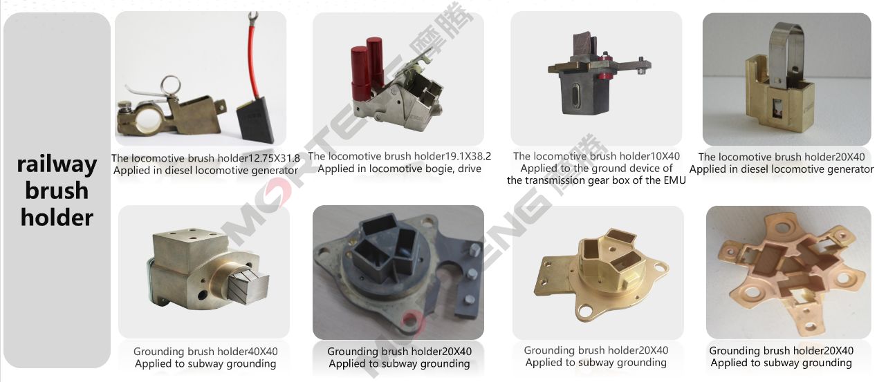
Phillipp Schmid, Application Engineer, SKF
Since 2012, offshore turbines with total power outputs in excess of one GigaWatt (GW) have been coming on stream in European waters every year. According to WindEUROPE, Offshore wind in Europe saw a net 1,558 MW of additional grid-connected capacity installed in 2016. Electric Slip Ring
Despite the challenges of constructing offshore turbines, the capacity there is expected to grow as suitable land-based sites become scarcer and operators take advantage of the greater consistency of wind at sea. The output power of offshore turbines also tends to be greater than their land-based counterparts. According to WindEUROPE the average power output of offshore turbines installed in 2016 was 4.8 MW. Turbines of 9 MW or more capacity are now in the launching stage – Vestas’ V164-9.5 MW development is a prime example.
The generic turbine with a gearbox sports a two-point suspension provided by the two large bearings. The arrangement is used on turbines in the 6-MW range.
Offshore wind turbines also tend to have longer blades which impose greater forces on drivetrains. In addition, drivetrains and their bearings are at greater risk of corrosion due to the saltwater environment. Conducting maintenance offshore is difficult, potentially dangerous and costly, so operators are keen to reduce the frequency of maintenance visits, which places considerable demands on the rotor bearings and their ability to continue to function reliably in these conditions for long periods.
There are four common bearing design concepts for turbine rotor shafts. The first is a two-point suspension with a toroidal roller bearing on the rotor side and a spherical roller bearing on the generator side. This is used for turbines in the 6-MW category for example.
For higher performance classes, the trend is to use ‘rigid’ bearing arrangement that features a non-locating and locating bearing combining a cylindrical roller bearing and a double-row tapered roller bearing. Alternatively, a purpose-designed bearing that combines the two into one bearing, such as SKF’s Nautilus, or arrangements comprising two adjusted tapered roller bearings. In all cases, the design, materials of construction and mechanical geometries of these bearings will have a considerable impact on their ability to function reliably between maintenance intervals.
The generic turbine is designed with a three-point suspension. One point for the large mainshaft bearing and two other points on either side of the gearbox.
Other bearing features have also gotten attention. Bearing cages, for example, are generally made of machined brass or sheet metal, the latter being more often found in larger bearings. Where possible, cages are always installed in one piece, but for larger bearings, they may comprise rows of segments which are manufactured individually and positioned one behind the other. All types of cages can be inner-ring centered, which produces less wear and thus prolongs the service life of the bearing — clearly important where offshore wind turbines are concerned.
Gearbox bearings have also gotten upgrades. One of the most important recent advances is a surface chemical treatment that places black oxidation on the raceway. Compared with untreated bearings, black oxidized bearings can offer a range of benefits for wind turbine applications, including reduced risk of premature bearing failure caused by white etching cracks, greater resistance to chemical attack by the more aggressive components of some lubricants, lower hydrogen permeation, and improved resistance to corrosion. Moreover, black oxidized bearing surfaces can offer reduced friction, decreased risk of slip damage, and greater tolerance of poor bearing-lubrication.
The cut-away shows how one OEM handles a direct drive configuration with a two-point suspension, on either side of the rotor.
In addition to offshore environment, bearings must also cope with the potentially damaging effects of high electric currents. For example, wind turbine generators are equipped with frequency converters which pose a new set of problems for bearings. The three-phase, ac-voltage outputs of the converter take the form of a series of rectangular pulses, rather than true sine waves, with the result that the total of these voltages is not zero and that there is a common mode voltage. This common mode voltage can result in leakage currents to the generator rotor via its bearings, damaging raceways, and compromising lubricant properties.
To prevent the passage of these leakage currents, the rolling elements of generator bearings are constructed from ceramic materials, which also have a lower inertia than is possible with equivalent steel ball bearings. In addition to non-conductive rolling elements, bearings are also available with ceramic-coated rings, which provide additional insulation to prolong bearing service life.
For higher performance designs, the trend is to use a ‘rigid’ bearing arrangement. This combines a nonlocating bearing, a cylindrical roller design (just behind the rotor), with a double row tapered roller bearing (just before the gearbox). The turbine with gearbox moment bearing separates the gearbox.
Of equal importance is the ability of the turbine nacelle to align itself according to the wind direction and the blades to ‘feather’ in response to wind speed. These functions are supported by slewing bearings, which have also become larger with the rise in turbine power capacity. Double-row four-point contact bearings are normally deployed in blade feathering mechanisms, while the tower bearings are usually single-row, four-point contact bearings but there are new concepts in development due to the increasing blade length. These bearings are spray galvanized to prevent corrosion, and because of the extreme weather conditions of the offshore environment, they are also fitted with special seals.
The four profiles show how drivetrain design has evolved with outputs. Rotor diameters and nacelle weights are posted below each. Below that are figures for the turbine weights if the designs were enlarged for a 10 MW rating.The Direct Drive HTS, from AMSC, refers to high temperature superconducting, a material that promises to significantly reduce generator weight.
Browse the most current issue of Windpower Engineering & Development and back issues in an easy to use high quality format. Clip, share and download with the leading wind power engineering magazine today.
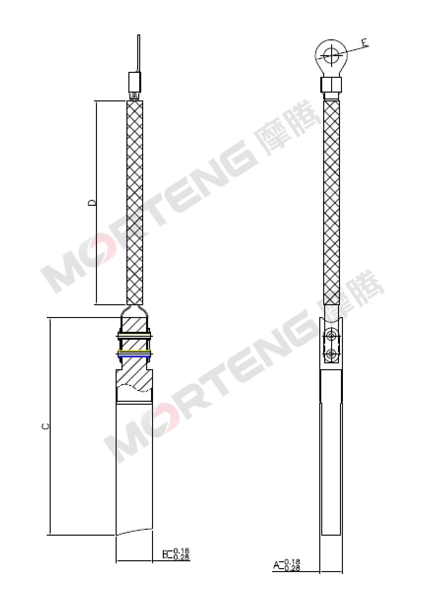
Brush With Holder Copyright © 2023 WTWH Media LLC. All Rights Reserved. The material on this site may not be reproduced, distributed, transmitted, cached or otherwise used, except with the prior written permission of WTWH Media Privacy Policy | Advertising | About Us